

Digital cartography
The research activities are focused on the following topics:
- cartographic generalization of buildings.
- cartographic generalization of contour lines,
- ....
1. Generalization of contour lines using energy-minimizing concept
doc. Ing. Tomáš Bayer, Ph.D., RNDr. Jakub Lysák, Ph.D.
Airborne Laser Scanning (ALS) represents a common method of data acquisition over large territories. 3D point clouds, used for the Digital Surface Model (DSM) construction, are very dense and not appropriate for the correct cartographic representation; they are over-detailed. The derived contour lines get too complicated shapes with artificial oscillations and zig-zag effects; they are noisy and not smooth enough and cannot be used directly in topographic maps of large scales. These artifacts primarily appear in flatter areas with the average slope less then 3 deg , the steeper territories provide more natural shape of contour lines.
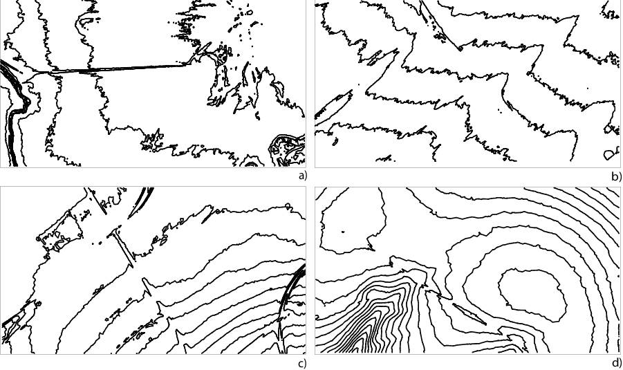
Illustration of oscillating raw contour lines due to terrain oversampling, derived from the 3D point cloud, depending on the slope α : the flat areas, a) α = 1. 0 deg , b) α = 1. 5 deg , the steeper territories, c) α = 2. 5 deg , d) α = 3. 0 deg .
There are several important cartographic rules and recommendations put on the simplified contour lines:
- R1: Important part of the relief should be preserved as much as possible.
- R2: Small details which are not reflected in neighboring contour lines should be smoothed out.
- R3: Adjacent contour lines in terrain with a constant slope should have similar spacing and an approximately parallel course.
- R4: The topological correctness is required. Except special cases neighboring contour lines never touch or intersect.
- R5: The vertical accuracy of the contour line should be preserved, the elevation of all contour line points lies within a given vertical threshold.
- R6: The contour line is naturally understood as a smooth line without oscillations, jumps and unnatural breaks. It looks neither jagged nor crooked nor oversimplified.
- R7: The position of simplified contour line should be as unchanged as possible, and only altered because of the clarity and readability of the map or compatibility with the map elements.
Vertical buffer.
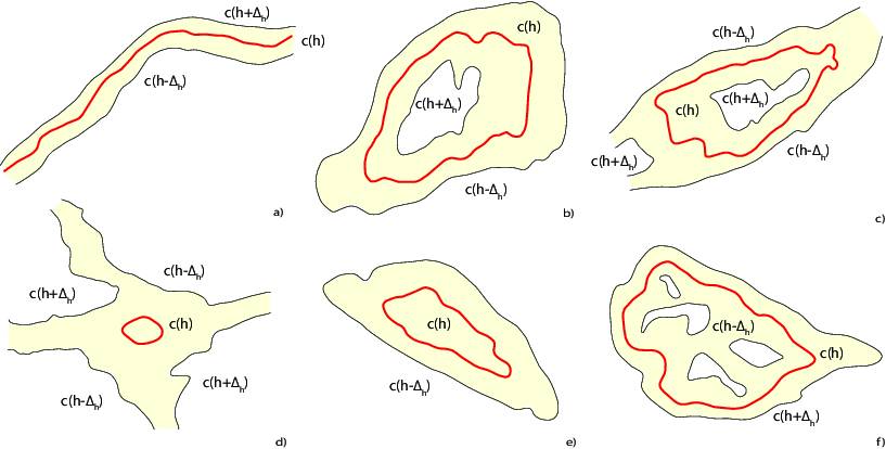
The vertical contour line buffer, introduced in as the error band, represents a natural geometric structure used in the simplification process of the contour lines. It establishes a connection between the positional and vertical errors, allows the construction of a supplementary corridor within which the simplified contour line c(h) lies [19]. The vertical contour buffer B(h,𝛥h), defined as the locus of points with the vertical difference of ±𝛥h from v , is formed by ``upper’’ c(h+𝛥h) and ``lower’’ c(h-𝛥h) contour lines.
Spline smoothing with the axial symmetry
A combination of smoothing, generalization and the symmetry according to the vertical buffer appear in the proposal of the new spline minimizing the total energy E=Ein+Eout , the sum of inner and outer energies. While Ein controls the deviation of the spline from the original line, Eout describes the impact of the constraint (the vertical buffer). The spline equations are complicated, for further information, see the References, please. From a cartographic point of view, the output contour line is smooth and as close as possible to the axis of the vertical buffer. Reflecting the shape of the vertical buffer, reducing the artificial oscillations, jumps, and breaks, this criterion will generate cartographically balanced results. However, some unnatural artifacts, such as over-smoothing, may occur; this issue will be removed by minimum energy spline. The proposed smoothing method also has a wide range of applications in computer graphics (determining the axis of symmetry or approximating topological skeletons, path optimization in narrow corridors).
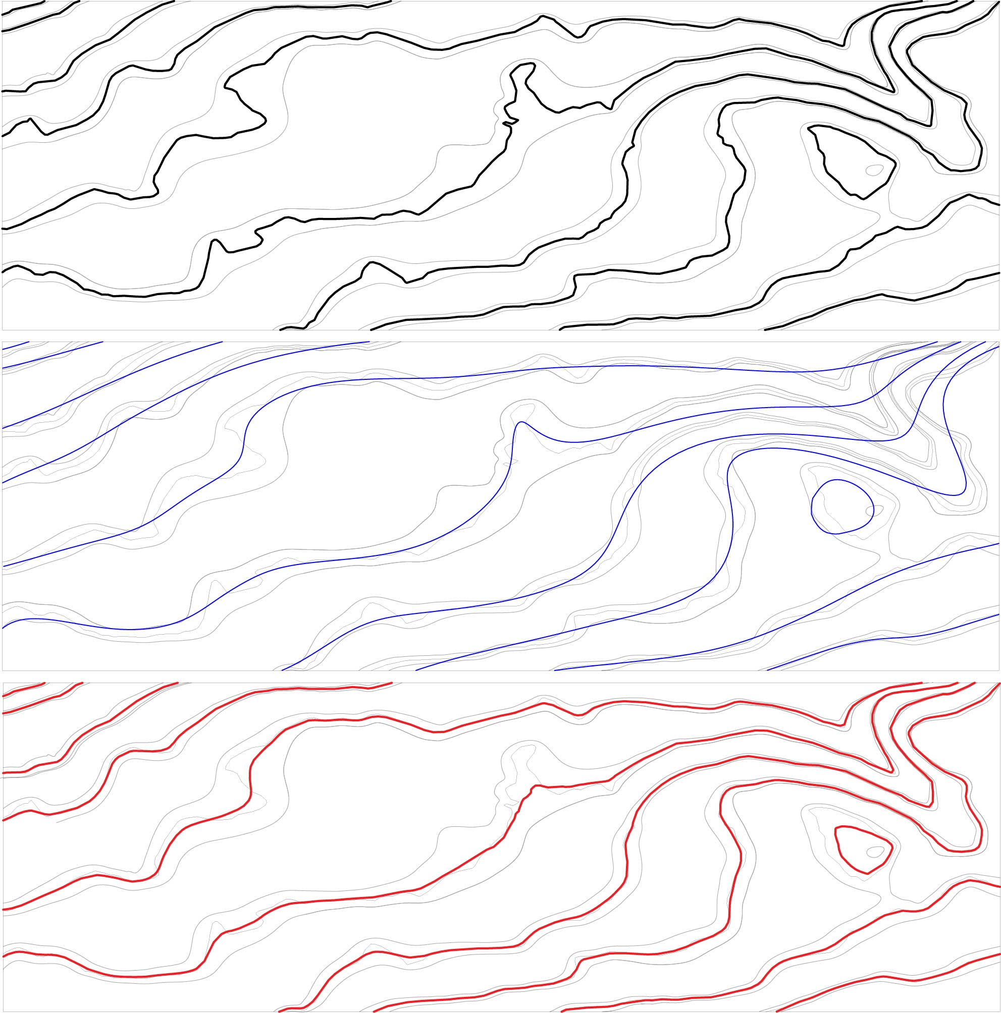
The first figure depicts the source contour lines (black) inside the vertical buffer (gray). The smoothing spline minimizing onky the internal energy Ein crossing the vertical buffer and thus violating the vertical errorm shows the second picture. The final solution (red) minimizes the total energy E is smooth and cclose to the axis of the vertical buffer.
Comparision to current methods. Compared to the Douglas-Peucker or Bend Simplify methods; both in constrained versions with barrier polygons represented by vertical buffers, and raw contour lines (RAW) generated from the point cloud. While DP is well known for its ability to keep the shape, and BS creates smooth outputs with well-preserved curvature, our solution tries to combine the benefits of both methods. The spline provides the smoothest approximation resembling cartographically correct results, the contour lines have an almost constant vertical error in the absolute value (approx., $m_{h}=0.025$ m).

References:
[1] BAYER, T., KOLINGEROVÁ I., ČELONK, M., LYSÁK, J.: Simplification of contour lines, based on axial splines, with high-quality results, International Journal of Geographical Information Science, 37(7), pp. 1520–1554, IF 5.2.
X. Generalization of buildings using a recursive approach
doc. Ing. Tomáš Bayer, Ph.D.
The aim of the simplification algorithm is to find another building representation based on a rectangular polygon of the simpler geometric form (in general non convex). During the simplification process such edges, that are not significant in the map context, are removed. Simplified edges are replaced with the set of new edges of a simpler form, whose parameters are determined using the least squares method. The splitting procedure is performed on the basis of criterion σ calculated for each edge of the building. To determine the angle of rotation φ of the building, a smallest area enclosing rectangle is constructed.
In addition, we have the following requirements for the simplification algorithm:
- the ability to simplify a rotated building,
- self intersections removing,
- the ability to keep an area of the building,
- the regulation of the simplification factor by a user,
- ability to simplify non-convex shapes with more complex geometry.
Splitting criterion σ.
For an assessment of the geometric complexity of the edge a criterion based on the standard deviation σ is used. This criterion is calculated repeatedly for each detected edge of the building. It is compared with a maximum value of the criterion σ m a x . Value of the criterion depends on the geometric complexity of the edge, for more complex forms becomes of greater values. Until σ > σ m a x , each edge is recursively decomposed to the sets of new edges. However σ m a x represents a simplification criterion regulated by a user.
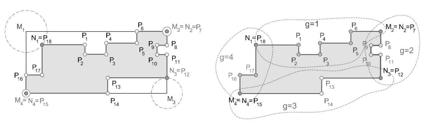
Hierarchical detection of vertices.
The presented algorithm is based on the idea of hierarchical detection of vertices. Vertices are detected on the basis of their geometric significance. New vertices are gradually added to the building, among them edges of the building are geometrically reconstructed. The idea of the algorithm is based on repeated search for such pairs or two pairs of points, that are located closest to the vertices of the smallest area enclosing rectangle, constructed over every edge. Those points will represent new vertices of the building in the next step. All points P i , which are located “between” two adjacent vertices, are matched all in all to the new edge.
A replacement of detected edges.
A split edge is intersected by the regression line at least in one point (except the case of collinearity). Such edge is decomposed to several new edges, whose end points are intersections of this simplified edge and the regression line. Those edges are called temporary edges. An idea of the splitting procedure is very simple. Each detected edge of the buildings will be replaced by the set of new edges of simpler geometric forms. Edges of such simple geometric forms, that can not be further split, will replaced by regression lines. Neighboring detected edges are perpendicular to each other. Splitting edges will be processed using recursive approach in the same way.
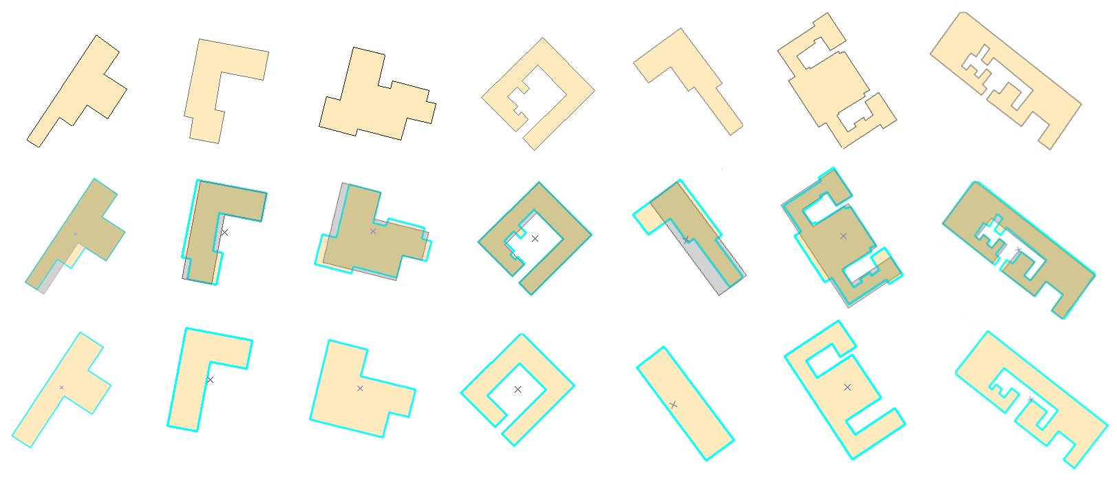
Cartographic assessment.
The presented algorithm gives cartographic results. It was able to simplify buildings with more complex geometry, sample data contained artificial polygons with hundreds of randomly generated vertices. In most cases, such buildings represent only geometric constructs. However, they generally verify abilities of the simplification algorithm. It also appeared, that the need for manual corrections of the simplification process is relatively rare (for rectangular buildings).
References:
[1] BAYER T.: Automated building simplification using a recursive approach. In: ICA Symposium on Cartography for Central and Eastern Europe, LNG&C, pp 121-145, Vienna, Springer, 2009, ISBN: 978-3-642-03293-6. Draft in PDF.
A long-term research interest in digital cartography concerns the representation of hypsography in topographic maps. We have been working extensively (but steadily) on the problem of rock representation (digital cliff drawing) since 2008. We do not aspire to compete with Swiss maps in terms of the beauty, as we are solving the task mainly from the point of view of the Czech state map series, using very schematic "ladder" style. The primary motivation for the research was the first mapping of elevation on the territory of the Czech Republic using lidar. We are trying to design automated procedures for drawing rock hachures. A more comprehensive Ph.D. thesis was also written about this issue, the results of which have been used in a number of mapping projects (Tetín, Srbsko). The improvement of our algorithms is still ongoing.
Within this topic, we also address the issue of large-scale representation of sandstone rocks, especially from data taken by drones. For perpendicular walls and rok pillars of our "rock cities", hatchures are not suitable, the contour method is a better choice. We have tried this and other methods in practice on several mapping projects (Kopicův statek, Vidim bridges).